Search results
Search for "reactive ion etching" in Full Text gives 62 result(s) in Beilstein Journal of Nanotechnology.
Design, fabrication, and characterization of kinetic-inductive force sensors for scanning probe applications
Beilstein J. Nanotechnol. 2024, 15, 242–255, doi:10.3762/bjnano.15.23

- -beam lithography and reactive-ion etching. We simulate the electromagnetic response of the meandering nanowire inductors using Sonnet, a quasi-3D electromagnetic simulator [32], which has the feature of including sheet kinetic inductance Lk,□. We begin by simulating the meandering inductor itself to


TEM sample preparation of lithographically patterned permalloy nanostructures on silicon nitride membranes
Beilstein J. Nanotechnol. 2024, 15, 1–12, doi:10.3762/bjnano.15.1

- layer on the resist, creating fences on the edge of the structure and contaminating the silicon nitride membrane. A possible solution is replacing IBE with reactive ion etching (RIE). Using RIE, there would be less redeposition since the reaction between gas and etched metal will form a gaseous compound


Spatial mapping of photovoltage and light-induced displacement of on-chip coupled piezo/photodiodes by Kelvin probe force microscopy under modulated illumination
Beilstein J. Nanotechnol. 2023, 14, 1059–1067, doi:10.3762/bjnano.14.87

- finalized by etching circular holes from the backside of the wafer to obtain thin membranes. The sizes of these holes were defined by applying and patterning a photoresist on the backside of the wafer, which was then anisotropically etched by deep reactive ion etching (DRIE) using SF6, O2, and C4F8 gases


Observation of collective excitation of surface plasmon resonances in large Josephson junction arrays
Beilstein J. Nanotechnol. 2022, 13, 1578–1588, doi:10.3762/bjnano.13.132

- using photolithography and reactive ion etching. The JJ sensor with variable thickness and a width of ≈100 nm is made by Ga+ focused ion beam etching. The JJ is made small in order to increase its resistance Rn to approx. 50 Ω, which is needed for a good impedance matching with the antenna. In order to


Coherent amplification of radiation from two phase-locked Josephson junction arrays
Beilstein J. Nanotechnol. 2022, 13, 1445–1457, doi:10.3762/bjnano.13.119

- self-aligning process using e-beam lithography and reactive ion etching [16][17]. Similar arrays were studied earlier in [9][12][13], where additional information about sample characterization can be found. Figure 1a,b shows the layout of “sample-1”. It has been fabricated on a 1 × 1 cm2 silicon


Double-layer symmetric gratings with bound states in the continuum for dual-band high-Q optical sensing
Beilstein J. Nanotechnol. 2022, 13, 1408–1417, doi:10.3762/bjnano.13.116

- structure can be fabricated as follows [56]. At first, the gratings of the bottom layer are fabricated using electron beam lithography (EBL) and reactive ion etching (RIE) on a SOI chip with a single crystalline silicon device layer and a buried oxide (BOX), where this SOI chip serves as the receiving


Roll-to-roll fabrication of superhydrophobic pads covered with nanofur for the efficient clean-up of oil spills
Beilstein J. Nanotechnol. 2022, 13, 1228–1239, doi:10.3762/bjnano.13.102

- using various dry/wet etching techniques including electrochemical HF etching, stain etching, metal-assisted etching, and reactive ion etching [9][11]. So-called “nanograss” or “black silicon” is a surface modification of silicon where the surface is covered with millions of tiny needle-like structures


Optimizing PMMA solutions to suppress contamination in the transfer of CVD graphene for batch production
Beilstein J. Nanotechnol. 2022, 13, 796–806, doi:10.3762/bjnano.13.70

- to the surface of the chips. A stopping layer (Cu/AlSiCu/TiW) for the reactive ion etching (RIE) process was sputtered, and the SiO2/SiNx multistack passivation layer was deposited by CVD. The passivation layer was patterned by lithography and etched by RIE until revealing the stopping layer on the


Fabrication and testing of polymer microneedles for transdermal drug delivery
Beilstein J. Nanotechnol. 2022, 13, 629–640, doi:10.3762/bjnano.13.55

- to grow to $50.6 billion by 2025 [6]. To enable mass manufacturing of MNs, factors such as reproducibility, fabrication precision, lower production cost, and time should be addressed. For instance, manufacturing techniques such as reactive ion etching and deep reactive ion etching incorporate


An overview of microneedle applications, materials, and fabrication methods
Beilstein J. Nanotechnol. 2021, 12, 1034–1046, doi:10.3762/bjnano.12.77

- biotherapeutics, drugs, and vaccines through the skin. A wide range of microneedle structure, design, geometry, and microneedle array densities is manufactured using different rapid prototyping and microfabrication technologies such as deep reactive ion etching (DRIE) [2], lithography [3], hot embossing [4], and
- injection moulding [61], wet chemical etching [75], reactive ion etching [2][76], hot embossing [4][5], laser drilling [77], lithography plus electroforming [78][79], drawing lithography [80][81], two-photon polymerization [5][82], and 3D printing [83][84]. To date, DRIE of silicon; micromoulding
- mask which must be compensated for in the pattern design. Anisotropic etching uses either EDP (ethylenediamine pyrocatechol), hydrazine-based solutions or, most commonly, potassium hydroxide solution. Deep reactive ion etching of silicon is an increasingly common process, performed in a low-pressure


In situ transport characterization of magnetic states in Nb/Co superconductor/ferromagnet heterostructures
Beilstein J. Nanotechnol. 2021, 12, 913–923, doi:10.3762/bjnano.12.68

- were used for the calibration of the etching rates of the films. MLs are patterned into micrometer-scale bridges with multiple contacts using photolithography and reactive ion etching. A scanning electron microscopy (SEM) image of one of the studied samples is shown in Figure 1a. Control of the


Electron beam-induced deposition of platinum from Pt(CO)2Cl2 and Pt(CO)2Br2
Beilstein J. Nanotechnol. 2020, 11, 1789–1800, doi:10.3762/bjnano.11.161

- exceeding the maximum pressure allowed in the SEM chamber (approximately 10−4 mbar). A silicon substrate was used for all deposition experiments, patterned such that circular areas of pristine silicon are surrounded by black silicon (obtained by reactive ion etching). The black silicon area aids in focusing


Walking energy harvesting and self-powered tracking system based on triboelectric nanogenerators
Beilstein J. Nanotechnol. 2020, 11, 1590–1595, doi:10.3762/bjnano.11.141

- transportation control, and for environmental monitoring. Experimental Surface modification of a PTFE film The surface modification of a PTFE film was performed in a similar manner as described previously [34]. Deep reactive ion etching was employed to construct PTFE nanowires aligned on the surface. Isopropyl
- electrode. Through deep reactive ion etching, polymer nanowires (average diameter of ≈150 nm and length values ranging from 410 to 680 nm) were created to vertically align on the surface of the PTFE film, as shown in Figure 1b. This modification on the PTFE surface not only enhances the effective contact


Fabrication of nano/microstructures for SERS substrates using an electrochemical method
Beilstein J. Nanotechnol. 2020, 11, 1568–1576, doi:10.3762/bjnano.11.139

- lithography (EBL) and wet etching consists of 1 μm deep square-based pyramidal pits in the silicon surface. A rhodamine solution (10−4 mol·L−1) is then detected using the Klarite substrate. Candeloro et al. [24] employed EBL and reactive ion etching to machine nanoholes of 400 nm diameter and 50 nm depth
- and reactive ion etching methods [25]. The Raman intensities of R6G and 4-mercaptopyridine molecules were measured by using different substrates. In addition, the Raman intensity of R6G on the pyramid structures was higher than that of R6G on the other structures in the experiment, and the enhancement


Wafer-level integration of self-aligned high aspect ratio silicon 3D structures using the MACE method with Au, Pd, Pt, Cu, and Ir
Beilstein J. Nanotechnol. 2020, 11, 1439–1449, doi:10.3762/bjnano.11.128

- layers have been patterned with standard photo-resist and a proximity lithography step. The selected full wafer pattern consists of a series of open quadratic test fields. These were transferred from the photo-resist to the PMMA layer using a reactive ion etching process with oxygen. In contrast to the


Integrated photonics multi-waveguide devices for optical trapping and Raman spectroscopy: design, fabrication and performance demonstration
Beilstein J. Nanotechnol. 2020, 11, 829–842, doi:10.3762/bjnano.11.68

- waveguides is completely decoupled from the silicon substrate. Then, a 100 nm thick layer of Si3N4 is deposited using low pressure chemical vapor deposition (LPCVD, Figure 5b). This layer is patterned using optical lithography and reactive ion etching (RIE) in a fluorine-based plasma, which is followed by
- (compare Figure 4b) using deep reactive ion etching (DRIE). This is a critical step, since the etch goes 14.3 µm deep down to the substrate, through all the device layers, including the waveguide circuitry at two levels. The etch is highly anisotropic and produces smooth walls of the microbath and thus
- 35 nm as a result of the tapering down. For reference, the original waveguide thickness of 100 nm is indicated in d) as well (dashed part). In step i), the side channels of the microbath, etched using the same deep reactive ion etching (DRIE) procedure, have been omitted. The thickness of the various


Hexagonal boron nitride: a review of the emerging material platform for single-photon sources and the spin–photon interface
Beilstein J. Nanotechnol. 2020, 11, 740–769, doi:10.3762/bjnano.11.61


Deterministic placement of ultra-bright near-infrared color centers in arrays of silicon carbide micropillars
Beilstein J. Nanotechnol. 2019, 10, 2383–2395, doi:10.3762/bjnano.10.229

- ], nanopillars in 4H-SiC formed by reactive ion etching (RIE) for the improvement of the VSi emission collection efficiency [50], and the use of a solid immersion lens (SIL) for an enhancement factor of three of single VSi [4]. Recent results of the successful enhancement of VSi in 4H-SiC based on nanopillars


Integration of sharp silicon nitride tips into high-speed SU8 cantilevers in a batch fabrication process
Beilstein J. Nanotechnol. 2019, 10, 2357–2363, doi:10.3762/bjnano.10.226

- silicon oxide and the LSNT layers are patterned by photolithography to cover only the etched pits. (iv) Deep reactive ion etching (DRIE) is used to etch the silicon vertically and laterally (4 and 1 µm, respectively) in order to provide access for the SU8 polymer to fill the base of the tips in the


Development of a new hybrid approach combining AFM and SEM for the nanoparticle dimensional metrology
Beilstein J. Nanotechnol. 2019, 10, 1523–1536, doi:10.3762/bjnano.10.150

- silicon wafers. The technique is based on using a direct-writing system (Raith-Vistec EBPG 5000+ electron-beam lithography system) and PMMA resist. After developing, the mask is transferred using RIE (reactive-ion etching). The P900H60 grating is used as a transfer standard and was calibrated by means of
- -writing system and a PMMA resin in which various patterns are then made by reactive ion etching (RIE). Some tests were also carried out with lift-off techniques for metallic deposition, but the results were found to be less conclusive for the deposit. Results and Discussion Repeatability of AFM and SEM


Renewable energy conversion using nano- and microstructured materials
Beilstein J. Nanotechnol. 2019, 10, 771–773, doi:10.3762/bjnano.10.76

- : materials and devices” covers the photo-electrochemical growth of platinum catalysts at plasmonic hot spots [6], the laser-assisted local growth of chalcopyrite absorbers [4], the preferential reactive ion etching of silicon by morphological anisotropies [5], the oxidation of copper nanoparticles resulting
Geometrical optimisation of core–shell nanowire arrays for enhanced absorption in thin crystalline silicon heterojunction solar cells
Beilstein J. Nanotechnol. 2019, 10, 322–331, doi:10.3762/bjnano.10.31

- array. The standard manufacturing procedure of c-Si heterojunction solar cells was followed, with the only addition of a cost-effective mask-less reactive ion etching step to create nanowires on the surface of the p-type Si wafer. The resulting 5 × 5 mm2 cell exhibits a best-device efficiency of 11.8
- characterisation The nanowire array was manufactured on a p-type mono-crystalline silicon wafer by reactive ion etching (RIE) using a gaseous mixture of SF6 and O2, followed by standard cleaning, rinsing in de-ionised water and drying of the substrate. In particular, the SF6/O2 plasma provides a continuous flow of


Femtosecond laser-assisted fabrication of chalcopyrite micro-concentrator photovoltaics
Beilstein J. Nanotechnol. 2018, 9, 3025–3038, doi:10.3762/bjnano.9.281
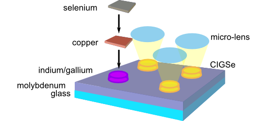
- layer was always observed. In order to avoid the undesired formation of a thin CuGaSe2 layer connecting the separate CIGSe islands after processing, this gallium wetting layer was removed by a mild reactive ion etching step in Ar+ plasma. LIFT approach The second approach presented here for the
- approach (left) to CISe micro absorbers (middle and right). Scheme of the process for manufacturing solar cells from microabsorbers. a) CISe absorber, b) spin coating of photoresist (insulator), c) reactive ion etching in Ar+ plasma, and d) addition of CdS and ZnO buffer layers and Al:ZnO front contact
- CIGSe islands, it is necessary to remove the uppermost part of the SU8 layer, such that the top of the islands is exposed. Upon choosing an appropriate initial viscosity, the SU8 layer is significantly thicker on the substrate than on top of the islands. Therefore, a mild treatment by reactive ion


Metal–dielectric hybrid nanoantennas for efficient frequency conversion at the anapole mode
Beilstein J. Nanotechnol. 2018, 9, 2306–2314, doi:10.3762/bjnano.9.215

- patterns are transferred on the resist with a second lithography step. Two non-selective etching processes are then performed: a first CHF3-mediated reactive ion etching (RIE) removes the 3 nm SiOx layer which is no longer needed, while the second inductively coupled plasma RIE with SiCl4/Ar gas treatment


Self-assembled quasi-hexagonal arrays of gold nanoparticles with small gaps for surface-enhanced Raman spectroscopy
Beilstein J. Nanotechnol. 2018, 9, 1977–1985, doi:10.3762/bjnano.9.188

- , different techniques such as reactive ion etching, thermal evaporation and atomic layer deposition can be used in combination with BCML [13][14][15]. Here it is important to choose the optimum chain length of the diblock copolymers for obtaining the desired inter-particle spacing [16][17]. It is thus
- ) chloride (KAuCl4, 0.1 wt %, Sigma-Aldrich), to grow the gold precursor particles with the electroless deposition process. Reactive ion etching (Oxford Plasmalab 80 Plus) was used to remove the polymer with an oxygen plasma treatment with the following settings: process pressure 100 mTorr, power 100 W


